Success Story
Managed Switch Used with EtherNet/IP Controller in Automated Material Handling System
When a major commuter railroad looked to modernize its 20-year-old automated material handling system in one of its maintenance facilities, the System Integrator (SI) chose an industrial-grade, Ethernet managed fiber optic switch from Contemporary Controls of Downers Grove, Illinois to connect the control equipment to the network.
The maintenance facility has 14 parallel tracks inside the building, and each one can accommodate six cars at a time. All maintenance and any upgrade to the trains is performed at this facility. In addition, new trains are commissioned, and old trains are decommissioned and taken out-of-service at this shop.
Within the facility, seven subsystems comprise a fairly complicated automated material handling system. A subsystem is a piece of the system which is defined by the type of equipment and/or the function of the equipment. The following six subsystems work together allowing parts and supplies needed for train maintenance to be received, stored and delivered to the appropriate area of the facility when required:
- Receiving Conveyor
- Unit Load Storage/Retrieval Machines
- Unit Load Conveyor System
- Mini Load Storage/Retrieval Machines
- Mini Load Conveyor System
- Central Monitoring System
The seventh subsystem (the Train Movement Alarm System) manages the movement of train cars in and out of the facility.
The two unit load storage/retrieval machines store pallet loads in a steel rack structure that is approximately 90 feet high and 300 feet long. The two mini load storage/retrieval machines store smaller parts in metal pans in a rack that is approximately 40 feet high and 200 feet long. The conveyor systems are pallet conveyor. They are made up of roller sections with chain transfers.
The SI Senior Lead Engineer said the modernization of the system was primarily driven by the difficulty of getting service for control equipment and the inability to purchase replacement parts.
"The customer's requirements of the system had changed," said the SI Lead Engineer, "And much of the material handling equipment, such as the storage/retrieval machines, was worn out. There was an overwhelming desire to take advantage of new technology."
This facility and the material handling system would remain in operation during the implementation of the modernization project. A detailed schedule was created to modify individual pieces or subsystems on off-shifts and scheduled periods of downtime. This required careful coordination with production personnel.
Because this was an existing system, there were potential limits on the amount of new technology which could be incorporated. All communications between these subsystems and manager computers were required to use the customer's existing WAN. Manager computers are located at a remote facility (3 to 5 miles away). They are basically responsible for parts inventory and daily work schedules. They also issue requests to the material handling system to store/retrieve/move parts.
The SI replaced the existing data highway communications between the PLCs and computers with EtherNet/IP technology.
"We were all pleased with the end result," commented the Senior Lead Engineer. "EtherNet/IP was faster, easier to maintain, relatively inexpensive, and a large variety of components were readily available."
Various outdated PLCs were replaced with modern PLCs. In addition, a number of HMIs were installed to aid in troubleshooting and maintenance.
The use of fiber optics was dictated by the large distances in the facility. One of the PLCs was well over 1,000 feet from the control room, and taking into account cable routing, it was even further.
The SI chose the Contemporary Controls EICP8M-100T/FC switch because it was able to deliver transmissions up to 2 km in distance and was immune to EMI/RFI. The EICP8M-100T/FC is a 10/100 Mbps switching hub with a mix of six auto-negotiating twisted-pair copper ports and two 100 Mbps multimode fiber ports with SC connectors. It is suited for applications where 0°C to +60°C temperatures are expected.
"Its compact size and DIN-rail design made it easy to install in the control cabinets," added the Senior Lead Engineer. The size of the switch is only 5.2" H x 3.8" W x 3.4" D (130 mm x 95 mm x 85 mm).
Designed with the conventional features in standard Plug-and-Play (PnP) switches, this switch includes important benefits such as IGMP snooping and query functionality, VLAN, Quality of Service (QoS), port mirroring, rate limiting, port security, and the Simple Network Management Protocol (SNMP).
IGMP snooping automatically limits IP multicast traffic to ports that require this traffic. This inhibits multicast traffic from overwhelming devices that should not receive this traffic - an important issue in EtherNet/IP networks.
In this application requiring maximum uptime for the communication network, the switch offers three possible redundancy solutions: RapidRing®, Trunking and RSTP (Rapid Spanning Tree Protocol). RapidRing allows building a redundant Ethernet network that will self heal in less than 300 ms. Trunking provides recovery from a single fault with a 10 ms or less recovery time. It also allows more bandwidth between switches. RSTP is a standardized method of creating redundant paths for data transmissions to create a higher level of reliability. Recovery time is typically one second or more.
Configuration is accomplished through a web browser via any Ethernet port or by using the terminal mode via the local console port.Port parameters, feature configuration, and device status can be modified and monitored by these access methods.
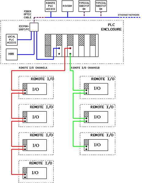
The fiber switch was the ideal solution because fiber optic cable was provided and installed by the customer. This is a large facility and individual subsystems are spread out over the area. Each subsystem has at least one PLC and one HMI connected to the network. An EICP8M-100T/FC switch is installed in each of the control cabinets to connect the equipment to the network. The communications diagram (below) is of the train movement alarm system. The seven PLC panels house remote I/O. An HMI is located in each PLC panel. Three of the new seven PLCs have remote I/O of various types which are not in the PLC enclosure. The Ethernet switch is inside the PLC enclosure. Various segment lengths of fiber optic cable (hundreds of feet) make the connection.
The Senior Lead Engineer said this switch has worked well on this project. "After implementation of the switch and the other modifications, the updated system increases the number of parts which could be moved in a given period of time due to increased reliability. Before the project, the system was frequently down for an extended period of time. This also contributed to excessive overtime on the part of the material handling system maintenance personnel. Overtime is essentially non-existent now."